How to create a conceptual model of a system?
One of the most important task of an analyst is to turn the requirements provided by the client or user into a physical model.
There are many methodologies to represent business rules that will be implemented in an information system. On this post we will use the ER model.
INFORMATION SYSTEMS CONCEPTS
Within companies and organizations as a whole, all types of information are received, produced, processed and transferred. Depending on the context, the information is critical for the environment in which it is being treated.
Example: Insurance broker. The customer goes to an insurance broker to get an insurance for his vehicle. It is required for the customer to provide his data and the data of the vehicle he wants to be covered by the insurance. As soon as this information is received, an evaluation process is initiated (risk analysis, etc.)
Each organization depending on the type of organization has its way of handling information.
* Insurance broker.
* Bank.
* Real State Broker.
* Travel Agency.
Information always comes from some source, and that source can be a group of people, an object, or a single person.
Information sources are called entities. In order to have greater control of the information, it is necessary to group them by their origin.
DATA MODELING
In an environment where a very high volume of information is treated, it is necessary to define a way in which the information structures are well defined and to determine (explicitly or implicitly) the relationships between entities.
It is important to identify the way in which relationships occur.
An entity may relate directly to several other entities, or to just one entity, and in very rare cases it may not relate to any other entity.
Relationships are distinguished by their type.
The relationship can be 1 to 1.
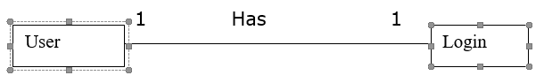
The above relationship represents the case of a user who has his login information (username and password) separate.
The relationship can be 1 to many

The above relationship represents the case of a class that contains several students.
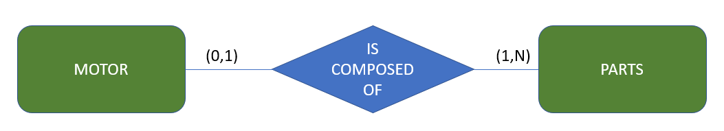
The relationship can be many to many

In the above relationship, we have the case of the teacher who teaches in several classes and the class that has classes with several teachers. This type of relationship generates a new entity.

Entity-Relationship Model (ER model).
The entity and relationship model is used to represent information, the owners of that information, and the relationships between that information.
Entity can be understood as a “thing” or something in the modeled reality, where information is kept in the database (DB). For example, in a school system, some entities might be students, teachers, timetable, subjects, and assessments. Note that an entity can represent both concrete objects (students) and abstract objects (timetable). The entity is represented by a rectangle, which contains the entity’s name. Look at the example below.
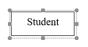
The Student entity represents all students about whom information is to be kept in the database. When it is necessary to specify a particular object (for example, a certain student) the term entity occurrence is used.
Relationship is a set of associations between entities. The relationship is represented by a diamond. This diamond is connected by lines to the rectangles that represent the entities participating in the relationship. The example below has two entities, DOCTOR and PATIENT, and a relationship called QUERY.

The above model informs that the DB maintains information about doctors, patients, as well as a set of associations (query), each one linking a doctor to a patient. When it is necessary to specify a particular relationship (for example, a particular query) the term relationship occurrence is used. A consultation occurrence involves the occurrence of a particular physician and the occurrence of a particular patient.
A relationship can involve occurrences of the same entity. In this case, we are facing a self-relationship. Look at the example:

MARRY is a relationship involving two occurrences of the entity PERSON. To facilitate understanding, we usually identify the role of each entity in the relationship (for example, husband and wife).
Cardinality is a number that expresses the behavior (number of occurrences) of a given entity associated with an occurrence of the entity in question through the relationship.
There are two types of cardinality: minimum and maximum. The maximum cardinality expresses the maximum number of occurrences of a given entity, associated with an occurrence of the entity in question, through the relationship. The minimum cardinality expresses the minimum number of occurrences of a given entity associated with an occurrence of the entity in the context through the relationship. We will use the following convention to express cardinality:


To read the model, we start from a certain entity and the cardinality corresponding to that entity is represented on the opposite side. In our example, the cardinality (0:N) refers to EMPLOYEE, while the cardinality (1:1) refers to DEPENDENT. This means that:
• An employee instance may not be associated with a dependent instance or may be associated with multiple dependent instances (a particular employee may have no dependents or may have several);
• A dependent instance is associated with only one employee instance (a given dependent has only one responsible employee).
Attribute is a relevant characteristic associated with each entity or Relationship occurrence. Note the notation used for attributes in the model below:

I hope you enjoyed this first part. In the next post we will talk about more advance topics of data modeling. God bless you. Have a good day.